
Electrical noise in oil and gas equipment can reach displays located near variable-frequency drives, motors, contactors, solenoid valves, switching power supplies, radios, generators, long field cables, and multiple grounding points. These systems can create conducted or radiated disturbances that are absent when the LCD, touch panel, or controller is tested alone on a short laboratory cable.
The resulting problem may not look like conventional electrical failure. An operator may see a brief flicker, a corrupted image, a display that loses its source, an intermittent touchscreen, an unexplained controller reset, or a system that works again after power cycling. Unless the disturbance path and operating event are recorded, the failure can be difficult to reproduce.
Electrical-noise resistance therefore belongs to the complete HMI design. The LCD, touch sensor, controller board, power supply, cables, connectors, shielding, chassis, grounding, firmware, host, enclosure, and installation must be evaluated as one signal and power system.
Quick Answer: Electrical noise can affect oil and gas equipment displays by causing flicker, lines, color errors, link loss, video-controller reset, backlight disturbance, missed or false touch, coordinate movement, USB or I²C disconnection, corrupted communication, and failure to restart correctly. Common sources include motor drives, relay and contactor switching, inductive loads, radio transmitters, electrostatic discharge, lightning-related surges, poor power quality, ground-potential differences, and unsuitable cable routing. Engineers should control the source, coupling path, and susceptible circuit through power architecture, filtering, separation, shielding, bonding, grounding, cable construction, connector design, firmware recovery, and production-intent EMC testing.
Claim: An electrically stable LCD module does not prove that the completed HMI will remain stable beside drives, radios, switching loads, long cables, and real equipment grounding. EMC performance is a system and installation property.
1. Which Electrical-Noise Sources Affect Oil and Gas Displays?
Electrical noise is a practical description for unwanted voltage, current, or electromagnetic energy that interferes with intended operation. Electromagnetic interference describes the disturbance, while electromagnetic compatibility describes the ability of equipment to operate satisfactorily without creating unacceptable disturbance for other equipment.
Direct answer: Oil and gas HMIs can be affected by conducted disturbances on power, signal, control, touch, and grounding paths; radiated fields from nearby transmitters and high-current equipment; inductive and capacitive coupling between cables; electrostatic discharge from personnel; switching transients; surge events; and voltage dips or interruptions. The credible sources depend on the exact equipment and installation.
How Do Motors and Variable-Frequency Drives Create Interference?
Motor drives switch voltage and current rapidly to control speed and torque. Their output cables, motor windings, input circuits, braking components, filters, and ground paths can produce common-mode and differential-mode disturbance over a wide frequency range.
A display cable routed beside a drive output or motor lead can receive coupled energy even when the two circuits are not electrically connected. Drive configuration, switching frequency, motor-cable length, cable shield, termination, bonding, and cabinet layout all influence the result.
What Happens When Relays, Contactors, and Solenoids Switch?
Interrupting current in an inductive load can create a rapid transient. Relay contact bounce and repeated switching can produce bursts that couple through power wiring, control lines, shared supplies, or nearby cable bundles. Symptoms may occur only when a particular valve, pump starter, or contactor changes state.
Suppression should be selected at the source where practical and coordinated with voltage, current, switching speed, release time, safety, and component life. A suppression device chosen without reviewing the load and control circuit can change operating behavior.
How Can Radios and Wireless Devices Affect the HMI?
Handheld radios, vehicle radios, cellular devices, wireless access points, telemetry transmitters, and other intentional RF sources can expose the display assembly and its cables to electromagnetic fields. A transmitter used close to the touchscreen or cable may create a different condition from a distant fixed antenna.
The test plan should identify transmitter type, frequency, power, antenna, permitted distance, duty cycle, and operating position. A generic radiated-immunity test may need additional application-specific evaluation when a radio is intentionally used close to the HMI.
Why Do Ground-Potential Differences Matter?
Equipment distributed across a skid, drilling system, pipeline station, or facility may not remain at exactly the same electrical potential. Long cables that connect devices bonded at different points can carry unwanted current through shields, signal returns, connector shells, or communication references.
The effect can include image noise, communication instability, touch errors, heating, or damaged interfaces. Protective earthing, functional grounding, signal reference, chassis bonding, cable shielding, and isolation are related but distinct functions that should be defined in the system drawing.
How Can Electrostatic Discharge Reach a Display?
An operator can discharge static electricity into exposed glass, a bezel, button, connector, or nearby metal. The current may follow the intended chassis path or find a path through the touch sensor, controller, cable, display electronics, or host.
Dry conditions, insulating clothing, footwear, floor materials, protective films, gloves, and cleaning methods can change static charging. A glass front does not remove the need for a controlled discharge path around edges, seams, printed regions, fasteners, and service openings.
Claim: Effective troubleshooting begins by identifying the source, coupling path, susceptible port, operating event, and recovery behavior rather than treating every flicker or touch error as an LCD defect.
2. How Does Electrical Noise Affect Image, Touch, and Control Electronics?
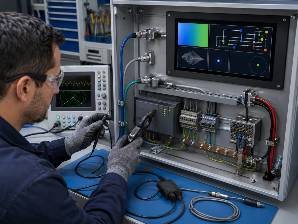
Noise can cause a visible disturbance without permanent damage, or it can reset, latch, degrade, or damage electronics. The same event may affect the display differently depending on image content, cable position, brightness level, touch state, software activity, and power sequence.
Direct answer: Electrical noise can disturb the pixel-data path, backlight power, controller logic, touch-sensing field, USB or I²C communication, host graphics output, and DC supply. Engineers should define whether each observed effect is permitted during exposure, whether automatic recovery is required, and whether any operator command or displayed state can become unsafe or misleading.
What Image Symptoms Can Electrical Noise Produce?
Possible symptoms include intermittent flicker, horizontal or vertical artifacts, sparkling pixels, color errors, image shift, loss of synchronization, black screen, backlight variation, link retraining, input switching, or complete controller reset. An external monitor input may also lose source detection or read display configuration incorrectly after a disturbance.
Some problems appear only at a particular resolution, refresh rate, cable length, or image pattern. Interface requirements for LVDS, eDP, MIPI DSI, RGB, HDMI, DisplayPort, DVI, VGA, USB, and I²C are reviewed in What Display Interfaces Are Used in Oil and Gas Equipment?.
Why Is Projected-Capacitive Touch Sensitive to Noise?
PCAP controllers detect small changes in an electric field. Display electronics, switching supplies, poorly referenced metalwork, cable coupling, radios, conducted RF, and ground movement can reduce the separation between a real touch signal and background disturbance.
Symptoms include missed input, false touches, repeated events, coordinate movement, delayed response, failure with gloves, or loss of touch after a transient. Firmware tuning can improve performance, but excessive filtering may reduce sensitivity or slow response. The production glass, gloves, grounding, LCD, controller, cable, and enclosure must be tested together.
How Can Power and Controller Disturbances Appear?
A controller board may reset, freeze, change input, corrupt a setting, lose EDID information, or fail to enable the backlight correctly after a supply disturbance. The host may continue running while the display controller restarts, leaving the operator without an image or with incorrect scaling.
Brownout thresholds, reset supervision, DC-DC behavior, stored energy, sequencing, firmware initialization, watchdogs, and nonvolatile settings influence recovery. Testing only steady-state voltage does not reveal all startup, interruption, and restoration problems.
Why Are Intermittent EMC Faults Difficult to Diagnose?
The disturbance may last microseconds while its effect remains until reset. A technician arriving later may find a blank screen or lost touch but no evidence of the initiating relay operation, radio transmission, ESD event, or supply transient.
Useful diagnostic evidence can include timestamped controller resets, input status, touch enumeration, host logs, power monitoring, drive events, alarm history, and video of the screen during testing. Replacing the LCD without identifying the path may leave the true cause unchanged.
Claim: A display EMC failure can affect image accuracy, touch commands, communications, settings, startup, and recovery. Pass criteria must cover function and operator consequences, not merely the absence of permanent damage.
3. How Should Engineers Design an Electrically Robust Display System?
EMC design is most effective when the team controls the source, interrupts the coupling path, and improves the victim circuit before enclosure and cable drawings are frozen. Late fixes can work, but they may add cost, heat, assembly variation, and untested interactions.
Direct answer: Engineers should define the electromagnetic environment, separate noisy and sensitive circuits, provide stable power and reset behavior, select the correct interface and cable, control return-current paths, coordinate shielding and bonding, protect every external port, manage the enclosure aperture and seam structure, tune touch only after the hardware is stable, and design deterministic recovery.
How Should Power Architecture Be Planned?
Separate sensitive display and touch power from noisy loads where required, while maintaining the grounding and isolation architecture. Review supply range, ripple, transients, common-mode voltage, inrush, backlight load changes, DC-DC switching, filtering, protective devices, and cable voltage drop.
Filters and transient protection should be selected for source and load impedance, frequency, voltage, current, energy, temperature, leakage, grounding, and failure mode. Component placement and return path can matter as much as the nominal part value.
How Should Cables Be Selected and Routed?
Use cable construction appropriate to the interface, including controlled differential pairs, impedance, twist, shield, ground conductors, connector shell, and length. Keep video, touch, and low-level control wiring away from drive outputs, motor cables, contactors, transformers, and high-current switching loops.
Where paths must cross, geometry and separation should be planned rather than left to final assembly. Restrain cables, preserve bend radius, avoid long shield pigtails where they undermine high-frequency performance, and keep service replacement routing consistent with the validated build.
Should Cable Shields Be Grounded at One End or Both Ends?
There is no universal answer. The correct termination depends on frequency, common-mode current, interface, cable length, isolation, enclosure, connector, equipotential bonding, safety rules, and the electromagnetic environment. A one-end rule copied from a low-frequency analog circuit may perform poorly for a high-speed digital display cable.
The system drawing should define shield continuity, connector-shell bonding, chassis connection, drain-wire treatment, and any intentional capacitive or direct termination. The decision should be verified by measurement and immunity testing in the representative installation.
How Do Enclosure and PCB Design Support EMC?
Conductive enclosure sections, bonded seams, controlled apertures, short chassis connections, filtered entries, gasket continuity, and appropriate connector mounting can provide a predictable current path. Coatings, corrosion, paint, anodizing, fastener choice, and assembly pressure can change bonding over the product life.
On the PCB, placement, layer stack, reference planes, return paths, decoupling, filtering, isolation boundaries, clock routing, I/O protection, and separation between backlight power and touch sensing influence performance. A strong enclosure cannot correct every poor internal current path.
How Should Touch Hardware and Firmware Be Coordinated?
Place the touch controller and route its sensor tail according to the sensor and controller requirements. Coordinate cover-glass thickness, printed area, nearby metal, LCD noise, chassis reference, power, host interface, cable shield, and firmware parameters.
Tuning should cover bare finger, every required glove, wet or contaminated surfaces where applicable, edge touches, repeated inputs, and EMC exposure. Touch integration practices are discussed further in How Do Touchscreens Improve Oil and Gas Equipment Operation?.
What Recovery Behavior Should Be Designed?
The HMI should return to a defined state after a permitted temporary disturbance. This may require power supervision, controller reset, watchdog logic, communication retries, touch re-enumeration, input redetection, backlight re-enable, and protection of configuration data.
Automatic recovery should not issue a command, conceal an alarm, change an authorized setting, or display stale process information as current. The host software, control system, and HMI should identify communication loss and recovery clearly.
Claim: Electrical robustness comes from coordinated power, interfaces, cables, routing, shielding, bonding, grounding, enclosure design, PCB layout, firmware, and recovery rather than one filter, ferrite, or shielding material.
4. How Should Display EMC Performance Be Tested and Validated?
Testing should reproduce the ports, cables, loads, operating modes, grounding, enclosure, and software of the production equipment. A bare panel has too few system elements to demonstrate the behavior of an HMI connected to a host, touch controller, external power supply, and real cable set.
Direct answer: Engineers should identify the applicable product or product-family standard first, then define disturbance phenomena, ports, levels, dwell, modulation, coupling method, cable arrangement, grounding, operating modes, monitoring, performance criteria, recovery, and test report requirements. Generic industrial EMC standards apply only where their stated conditions are met and no more specific standard governs the equipment.
Which EMC Tests May Be Relevant?
The applicable equipment requirement determines the final test set. The IEC 61000-4 series provides basic testing and measurement methods, while IEC 61000-6-2 provides generic immunity requirements for industrial environments when no relevant dedicated product or product-family immunity standard applies.
| Disturbance | Possible Field Source | Basic IEC Method | Display Behavior to Monitor |
|---|---|---|---|
| Electrostatic discharge | Operator or adjacent object | IEC 61000-4-2 | Image, touch, reset, recovery |
| Radiated RF field | Radio or wireless transmitter | IEC 61000-4-3 | Flicker, link, touch accuracy |
| Fast transient or burst | Relay, contactor, inductive switching | IEC 61000-4-4 | Reset, communication, image |
| Surge | Switching or lightning-related overvoltage | IEC 61000-4-5 | Damage, restart, retained settings |
| Conducted RF | RF coupled onto connected cables | IEC 61000-4-6 | Touch, video, USB or I²C stability |
These basic methods do not by themselves select the required level or performance criterion for a particular oil and gas product. The responsible manufacturer must use the applicable equipment standard, intended environment, installation, risk assessment, and certification plan.
Why Must Every External Port and Cable Be Represented?
Power, HDMI, DisplayPort, DVI, VGA, USB, Ethernet, serial communication, remote buttons, backlight control, and protective or functional earth can each provide a coupling path. Native LCD cables and touch tails inside the enclosure can also receive fields or carry common-mode current.
Use production-intent cable type, shield termination, connector, length, routing, load, peripheral, and grounding. An unused port should be configured as it will be shipped, while every required operating port should be exercised in representative modes.
What Should Be Monitored During Immunity Testing?
Monitor live image content, pixel integrity, video link, input selection, brightness, backlight, current, controller reset, touch enumeration, coordinate accuracy, false and missed touches, communication status, HMI software, and recovery. A camera can capture brief visual events that are missed during post-test inspection.
Test normal operation, alarm display, trend updates, permitted touch input, data communication, startup, shutdown, restart, and relevant maintenance modes. A static color screen alone may not expose an error in scaling, data refresh, touch mapping, or application recovery.
How Should Performance Criteria Be Defined?
Specify which temporary effects are allowed during each phenomenon, whether operator intervention is permitted, the maximum recovery time, and which functions must remain continuously available. No unintended command, corrupted configuration, misleading process state, or uncontrolled restart should be accepted.
Criteria should distinguish a momentary visual artifact, temporary degradation with automatic recovery, loss requiring manual reset, and permanent damage. The equipment standard and system risk analysis determine which category is acceptable for each function.
Why Are Precompliance and Installation Testing Both Useful?
Development testing can locate weak frequencies, cable paths, enclosure seams, and susceptible ports before formal testing. Current probes, near-field probes, oscilloscopes, spectrum measurements, controlled transmitters, and transient monitoring can support diagnosis when used by qualified personnel.
Installation testing can reveal coupling from the actual drive, motor cable, radio, generator, grounding network, or cabinet arrangement. It complements but does not automatically replace required laboratory conformity testing. Both should use safe, documented methods that do not disturb other operating equipment.
How Do Hazardous Areas Affect EMC Work?
EMC immunity does not establish suitability for an explosive atmosphere. Shield bonds, protective components, filters, cable entries, glands, grounding, enclosure changes, added conductive gaskets, and electrostatic behavior can affect an assessed hazardous-area configuration.
Tests that create sparks, discharges, or abnormal electrical stress should be performed only in an appropriate controlled facility. The responsible equipment manufacturer and certification parties must review EMC changes against the explosion-protection concept and approved construction.
What Should Remain Under Configuration Control?
Control the LCD and revision, touch sensor and firmware, controller board and firmware, power supply, filters, protective devices, ferrites, cables, connectors, shield termination, grounding straps, conductive gaskets, enclosure coatings, fasteners, PCB revision, host, BIOS, drivers, operating system, HMI software, assembly drawings, and test configuration.
A cable, ferrite, gasket, controller, power module, or firmware change can alter EMC performance even when normal bench operation appears unchanged. Approved alternatives should be supported by documented engineering review and testing.
Claim: Meaningful EMC validation uses the applicable standard, production ports and cables, representative grounding and enclosure construction, active functional monitoring, explicit performance criteria, and controlled recovery.
5. What Advantages Does XIANHENG Offer for Oil and Gas Display Projects?
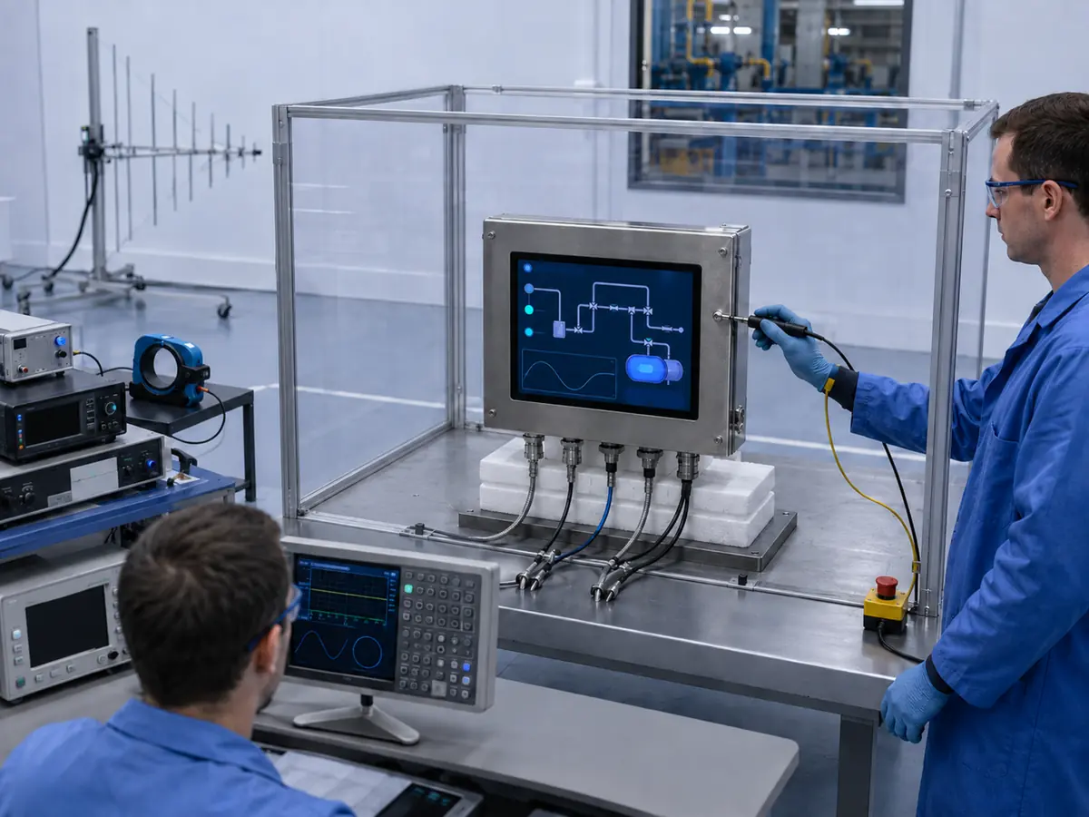
XIANHENG supports display integration for drilling, well-service, pumping, compression, metering, pipeline, refinery, offshore, and remote HMI equipment. Support can begin with a new architecture or an existing display that shows intermittent noise-related behavior.
Direct answer: XIANHENG can help customers compare industrial TFT LCDs and coordinate PCAP or resistive touch, customized cover glass, optical bonding, controller boards, firmware, interface conversion, connectors, customized cables, supported shielding and grounding details, drawings, samples, inspection, replacement analysis, and lifecycle planning. Customers can review panel starting points in the Industrial LCD Product Collection. Final EMC architecture, equipment conformity, hazardous-area approval, functional safety, and site installation remain with the responsible manufacturer and certification parties.
How Can XIANHENG Review a Display Signal Path?
Customers can provide the host output, LCD or monitor input, resolution, interface, controller, cable drawings, connector pinout, power architecture, touch interface, enclosure, grounding concept, nearby noise sources, failure symptoms, event timing, and existing test results.
XIANHENG can review supported display-side compatibility across timing, voltage, controller firmware, cable construction, connector direction, shielding, backlight control, touch connection, and startup behavior. This helps separate normal interface mismatch from a disturbance that requires equipment-level EMC work.
Can XIANHENG Coordinate Touch and Controller Firmware?
PCAP or resistive touch can be coordinated with the LCD, cover glass, bonding, touch controller, USB or I²C interface, cable, host, and mechanical stack. For PCAP, available firmware parameters can be reviewed against the required glass, gloves, liquid behavior, grounding, and electrical environment.
Touch tuning should be completed in the representative assembly and verified during equipment EMC testing. A firmware setting that suppresses noise should not be accepted if it creates missed input, slow response, or loss of glove performance.
How Can Customized Cables Support EMC Integration?
A controlled cable drawing can specify connectors, pin numbering, pair assignment, impedance-related construction, length, shield, drain wire, ground conductors, shell termination, labels, direction, bend limits, and strain relief. Samples can be prepared for image, touch, signal-integrity, vibration, and EMC evaluation.
The equipment manufacturer should validate the cable with its actual host, controller, enclosure, routing, grounding, drive environment, and regulatory test configuration. A cable that performs well outside the cabinet may behave differently after installation beside power wiring.
What Information Should Customers Send to Start?
Useful inputs include the equipment type, installation location, host and operating system, display size and resolution, native or monitor interface, touch method, controller, power input, cable types and lengths, grounding diagram, enclosure material, nearby drives and radios, switching loads, field wiring, observed symptoms, EMC requirements, classified or non-classified area, annual quantity, schedule, and lifecycle target.
To discuss an electrically robust oilfield HMI, drilling-control touchscreen, pump or compressor display, pipeline-station LCD, offshore monitor, controller-board solution, customized display cable, or obsolete-panel replacement, please reach out to XIANHENG.
Claim: XIANHENG supports oil and gas display EMC projects by coordinating the panel, touch, controller, firmware, interfaces, connectors, cables, drawings, samples, replacement work, production controls, and lifecycle while keeping final equipment responsibilities clearly defined.


